 Jonathan Mullen
I originally wrote this post in 2017 for the Illini Solar Car Blog which has gone offline. It is mirrored here to keep this info available.
One of the largest sub-teams we have at Illini Solar Car is our Solar Team. Our Solar Team is responsible for the fabrication, testing, and mounting of the the vehicle solar array. The solar array team is made-up of students from several engineering majors with Materials Science and Engineering having the largest representation. These students are currently hard at work fabricating each of the 20 modules that will be put together to form the array. The array is primarily put together in the ECE Building Clean Room with encapsulation taking place in the ECE Open Lab. Read below for a more detailed look into this process!
The Process of Creating a Solar Module
There are four main components that go into creating a solar array:
- Top Film
- EVA Film
- Solar Cells
- Back Sheet
Thank you to Isovoltaic for donating EVA and back-sheet and to Sunpower for giving us a discount on Solar Cells!
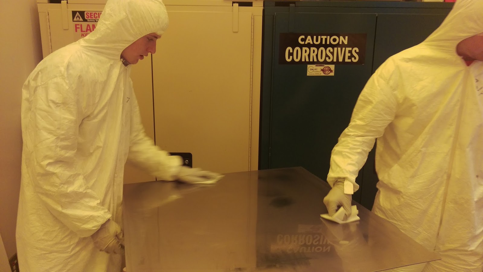
The process starts in the Clean Room in the ECE Building.
Each solar module is put together on a large stainless steel sheet. This sheet is first polished and then cleaned with Acetone and IPA (Isopropyl Alcohol). After the metal sheet is cleaned, top-sheet and EVA are cut, cleaned, and placed on the stainless steel with top sheet on the bottom (the array is assembled upside down). The top film is the clear outer polymer layer which acts as a shield from the outside world. Most commercial solar arrays utilize thick glass or plastic sheets as this outer layer. Solar vehicles, on the other hand, utilize top sheet to reduce weight and allow the needed flexibility for mounting the cells on the slightly curved vehicle bodies. Underneath the top sheet is the EVA film. EVA is ethylene vinyl acetate - a copolymer material. Upon encapsulation the EVA melts and essentially laminates the individual solar cells. This protects the solar cells from dirt, humidity, and other contaminants. Additionally, EVA helps to absorb shocks from objects that may hit the solar array (such as a rock kicked up by a leading vehicle).
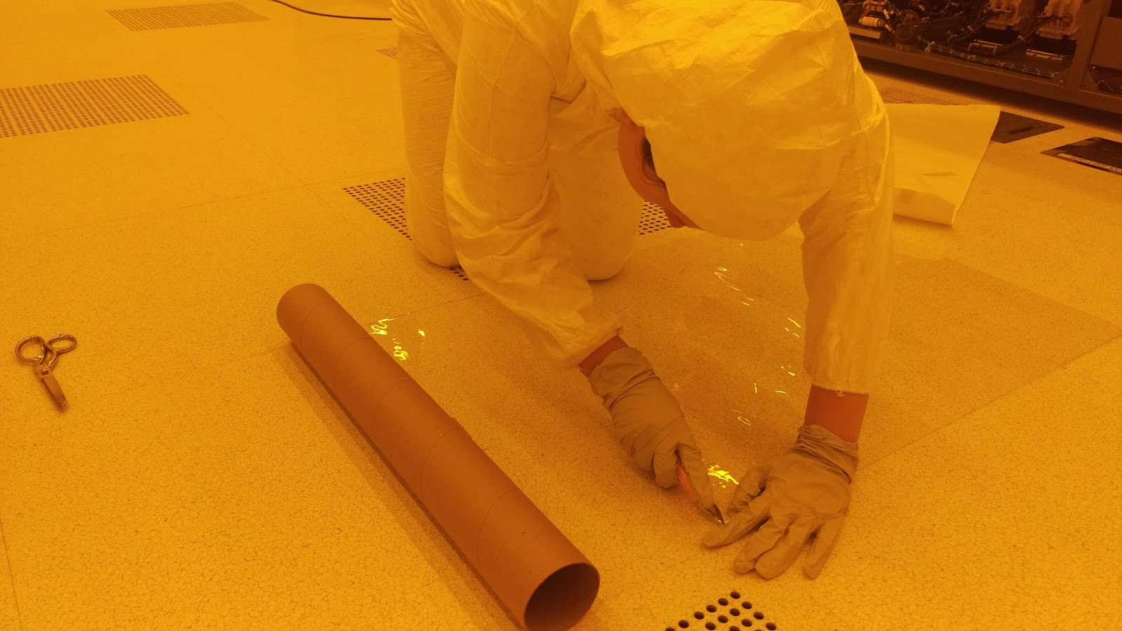
Cutting the Top Film
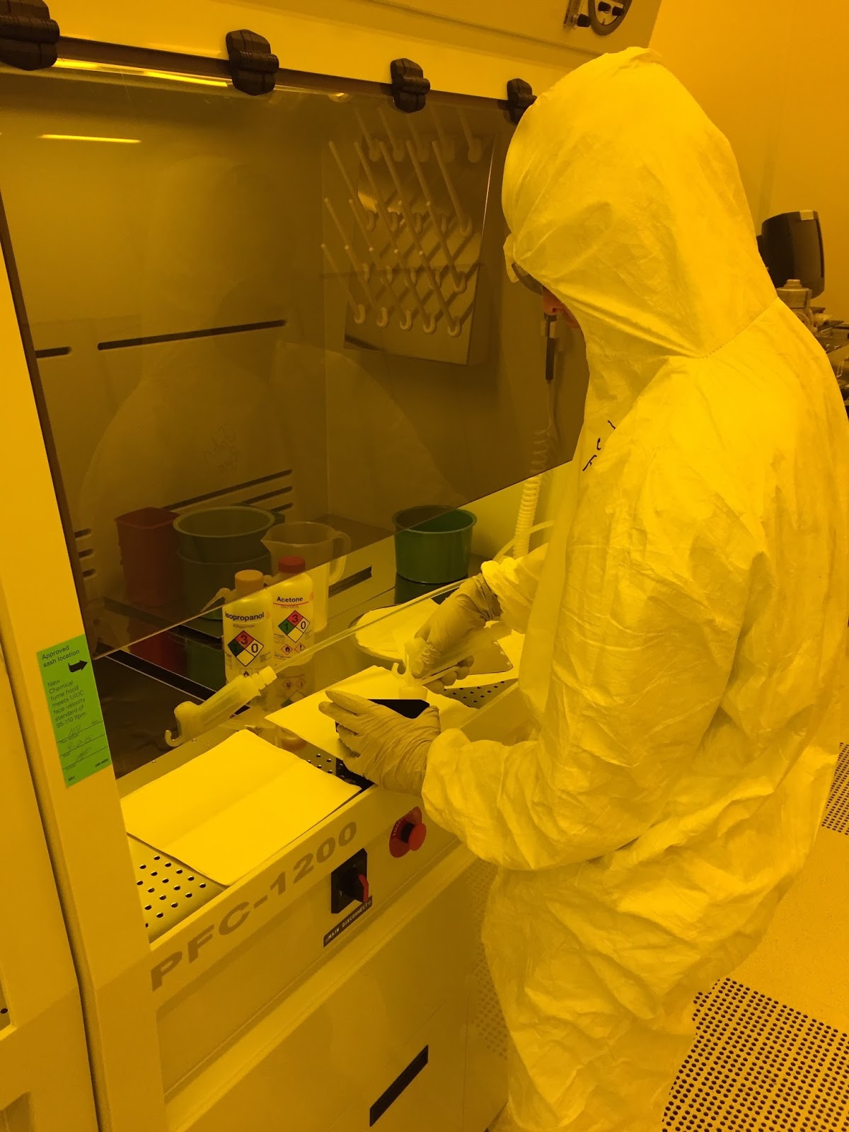
Once the top film and EVA are cut, cleaned, and placed onto the stainless steel, each solar cells must be cleaned. Each cell is rinsed with acetone, IPA, and deionzied water and then dried with pressurized nitrogen gas.

Washing Solar Cells in the Clean Room
Drying with nitrogen gas
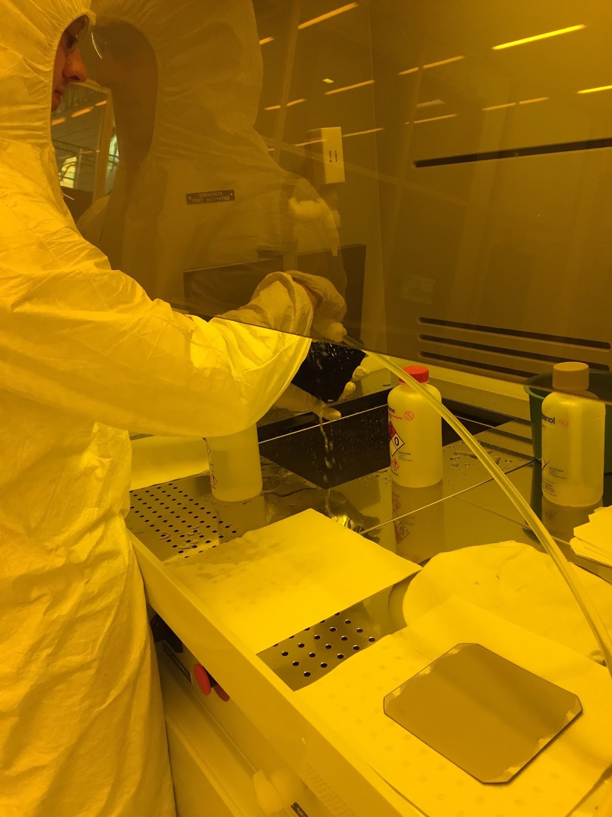
Rinsing with deionized water
After the cells washed they are laid out correctly for that specific module. There are 20 modules on the car - many of which are unique in some way. Modules are different shapes and have connections at different places due to constraints at different locations on the car. This module is a 4 x 6 module with a simple internal routing (zig-zag from one end to the other). Other modules, however, may not be rectangular or may have complex or inconsistent routing to fit their connections to the car.
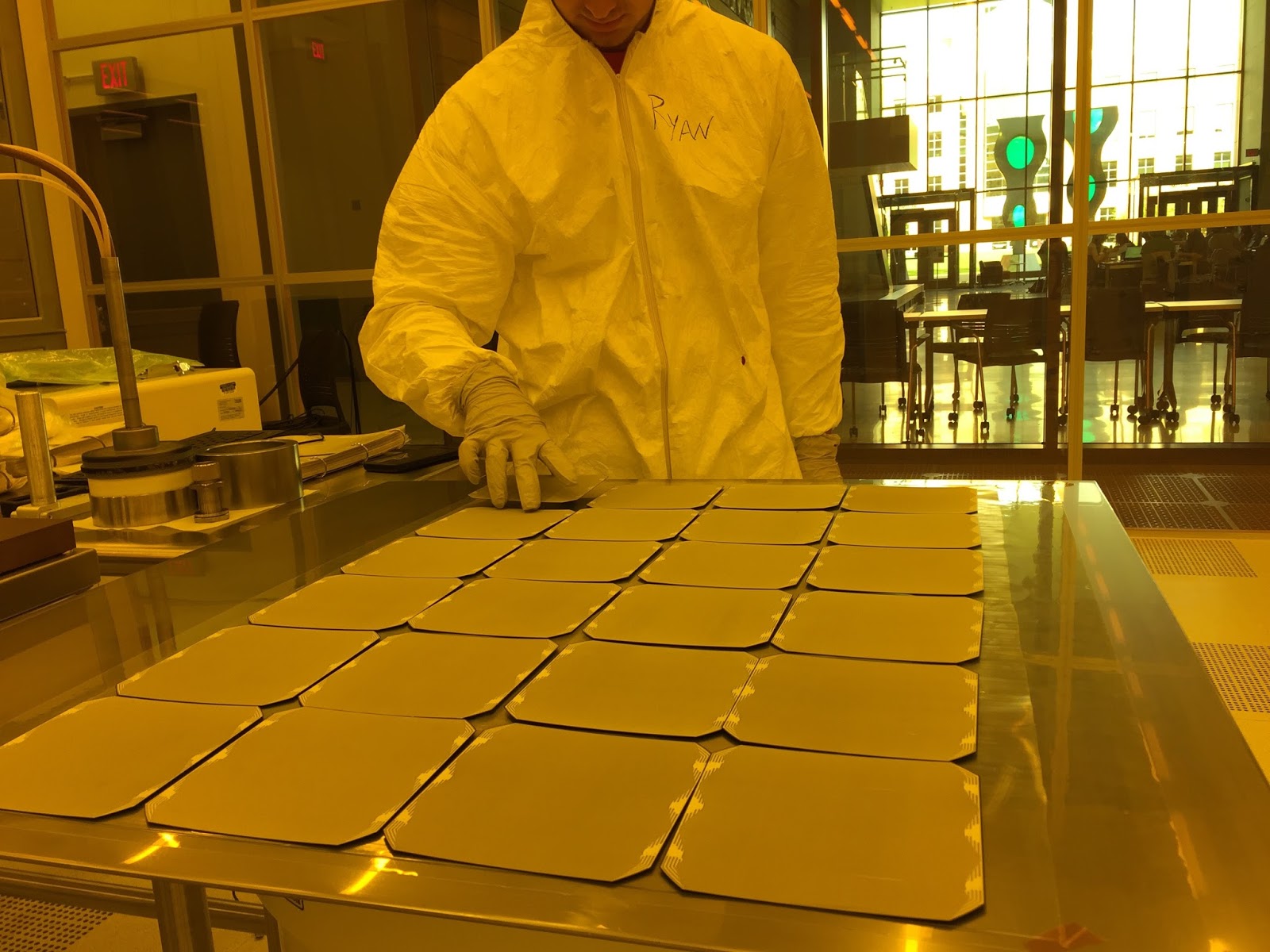
Placing the last cell of a 4 x 6 module
The module is next transferred to a different room within the clean room for soldering. Soldering is the most involved process of each module. Each cell has multiple connections to solder together. Additionally, the solderer must verify that cells are lined up correctly to ensure the module works as expected. Once the module is encapsulated nothing can be changed. One bad connection will render a module unusable on the vehicle. On a 4 x 6 module, like the one above, one bad connection will result in no output from 8 of the 24 cells.
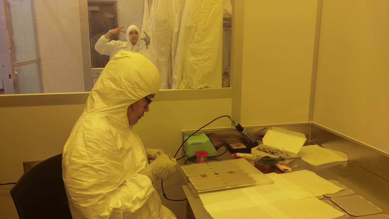
Soldering in the Clean Room
The soldered cells are then arranged back onto the top film and EVA as before. The last piece is the back sheet. The back sheet protects the wiring and the backs of the cells when the module is mounted onto the car. It also acts as an insulator since the body is made of carbon fiber - a conductive material. Now the module is fully assembled and it is transferred back to the ECE Open Lab where the module is encapsulated.
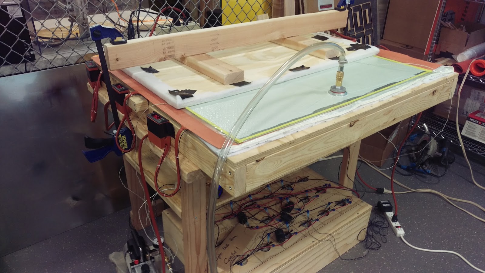
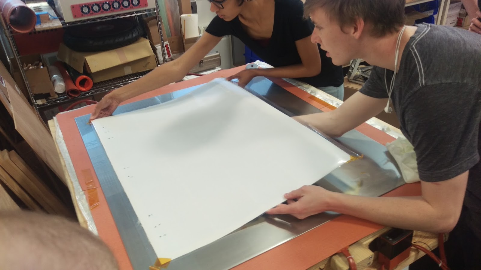
The encapsulation process involves placing the module under heat and pressure. First, breather material is placed on top of the module and the module is sealed inside vacuum bagging. Then a pump is attached to increase the pressure to as close to 29.92 Hg (inches of Mercury) as possible. We are able to reach levels above 28 Hg. Lastly, plywood is clamped down on top of the vacuum bagging. Together these provide the pressure and ensure the module is encapsulated flatly. Thank you to Airtech for donating the vacuum bagging materials!
The module is placed underneath the plywood while encapsulated
To heat the module, silicon heating pads are used. The heating pads are the red/orange pads underneath the stainless steel. The pads are incrementally increased to 135° C over the course of 30 minutes. The temperature is then left at 135° C for 60 minutes. The module is then left to cool (which can take a while). Once it reaches a temperature below 40° C, the vacuum and plywood are removed. Once cooled to room temperature, the vacuum bag and breather are removed and the module is complete!
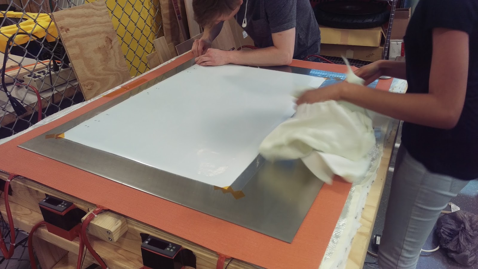
Removing Breather Material
Flipping over the module
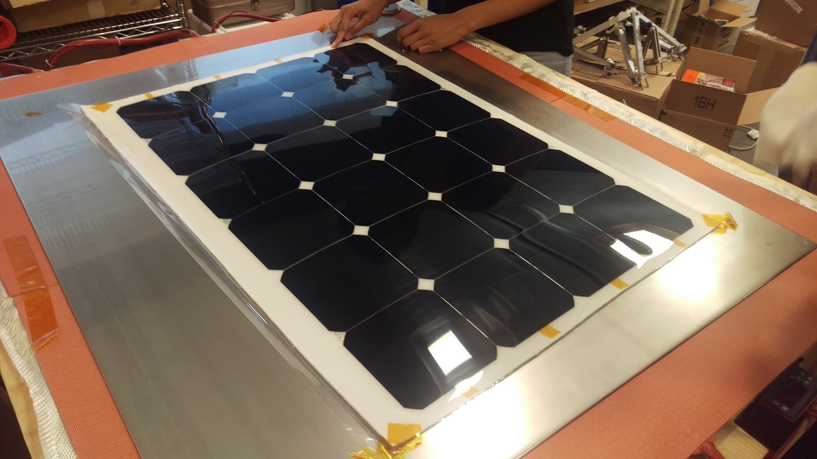
A completed 4x6 module!